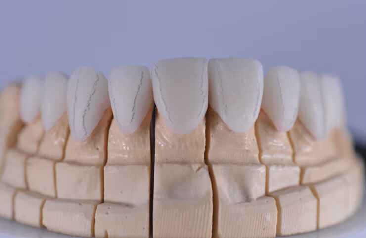
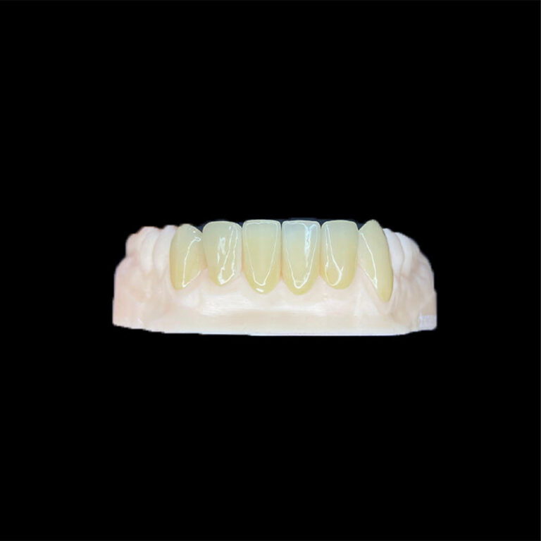
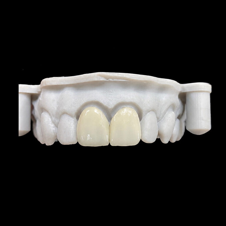
Transitional Line Angles in Veneers: The Hidden Tool for Optical Contouring
Dimensions can deceive.
A veneer may match the approved width to the tenth of a millimeter and still look broad, short, flat, or strangely dominant because the eye does not inspect ceramic with calipers; it reads the light returned by the facial surface.
So why do we keep treating mesiodistal width as the final answer?
My position is blunt: veneer line angles deserve the same attention as shade, incisal length, contact position, and ceramic selection. Yet they are often left to a generic CAD library or corrected during the final polish, when much of the facial morphology has already been committed.
That is backwards.
Veneer Line Angles Control the Tooth the Eye Sees
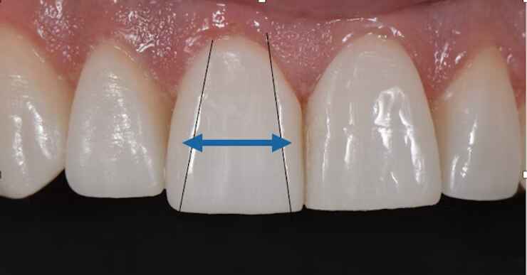
Transitional line angles are the curved facial crests where the visible labial surface turns toward the proximal surfaces. In anterior veneers, the two most influential lines are normally:
The mesiofacial transitional line angle
The distofacial transitional line angle
Together, they frame the central reflective zone. The surfaces outside those boundaries turn away from the observer and become deflective zones.
A line angle is not a groove. It is not a painted line. And it should not resemble a sharp ridge cut into the ceramic.
It is a controlled change in surface direction.
Reflective and deflective zones
The reflective zone is the part of the facial surface that returns light toward the observer. A broad, relatively flat reflective zone can make a veneer appear wider, brighter, and more prominent.
The deflective zones are the proximal facial surfaces outside the transition lines. They direct light away and visually remove mass from the edges of the tooth.
Move the mesial and distal line angles inward and the reflective zone becomes narrower. The veneer may then appear slimmer and, depending on its cervical and incisal contours, longer.
Move those angles outward and the reflection becomes broader. The same physical restoration may appear wider, flatter, and shorter.
This is optical contouring in cosmetic dentistry: controlling apparent dimensions by changing light behavior instead of simply cutting away ceramic.
Physical width is not esthetic width
Suppose two central incisors both measure 8.5 mm from mesial contact to distal contact. One has a 6.6 mm reflective zone; the other has a 7.3 mm reflective zone.
They will not look equally wide.
That difference becomes even louder when the wider reflective surface also carries excessive value or mirror-like gloss. Artist Dental Lab’s guide explaining why value matters more than the shade tab covers the related optical problem: brightness, line-angle position, facial convexity, and surface finish interact rather than operating as separate settings.
Correct shade does not rescue incorrect reflection.
What the Research Supports—and What It Does Not
The basic optical principle is defensible. The popular claim that every 0.2 mm line-angle adjustment creates a predictable visual result is not.
Three studies show why professionals should use line angles deliberately without pretending that optical contouring is an exact chairside equation.
A 4,264-tooth study measured “esthetic width”
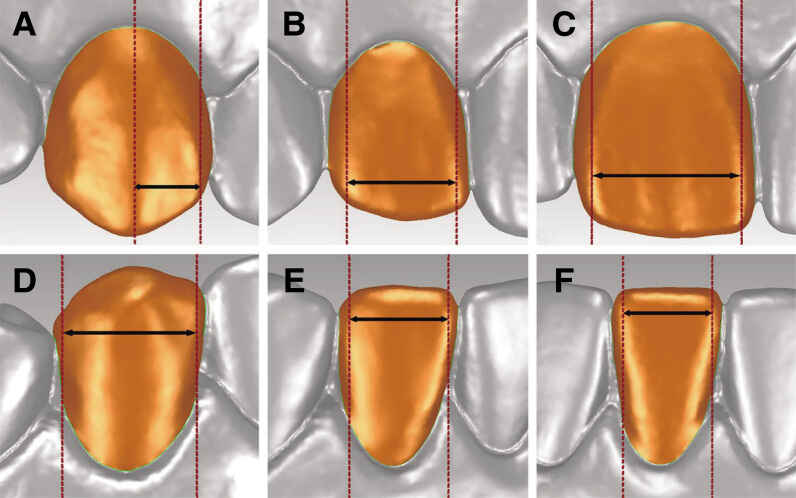
A 2022 observational study measured 4,264 maxillary and mandibular anterior teeth with Geomagic Studio software. The researchers defined esthetic width as the maximum distance between the mesial and distal labial transitional line angles.
The reported mean values were:
Maxillary central incisor: 6.773 ± 0.518 mm
Maxillary lateral incisor: 5.451 ± 0.487 mm
Maxillary canine: 3.340 ± 0.353 mm
Mandibular central incisor: 4.329 ± 0.331 mm
Mandibular lateral incisor: 5.008 ± 0.351 mm
Mandibular canine: 5.958 ± 0.415 mm
Except for mandibular canines, the study found no significant esthetic-width difference between corresponding teeth in the same arch. The full labial transitional line-angle biometry study is useful because it gives technicians measurable anatomical references rather than another vague instruction to “make it natural.”
But there is a catch. The measurements described a studied Chinese population. They are reference data—not universal targets for every ethnicity, facial type, tooth position, wear pattern, or patient-approved smile.
I would never instruct a technician to force every maxillary central incisor into a 6.773 mm reflective width. That would turn useful anatomy into bad dogma.
A 75-observer experiment complicated the optical-illusion claim
A 2017 study examined optical techniques used on a single composite-resin veneer closing a 2 mm maxillary central-incisor diastema. Researchers created six conditions, including no veneer, a veneer without illusion features, centralized interproximal ridges, curved incisal edges, mesial and distal gray pigment, and pigment over the developmental lobes.
The images were assessed by 75 people: 25 faculty members, 25 senior dental students, and 25 patients.
The overall technique did not produce a statistically significant difference in judging the central incisors as the same size, with (P = 0.869). Evaluator background was also not significant, with (P = 0.209). Centralizing the interproximal ridges reduced the estimated odds of the restored tooth being judged wider, but the result—adjusted odds ratio 0.59, (P = 0.088)—did not cross the conventional 0.05 threshold.
The PubMed-indexed veneer optical-illusion study therefore delivers an uncomfortable result: the theory is visually plausible, but its effect can be weaker and less predictable than confident lectures imply.
Photography size, smile-line height, adjacent anatomy, surface texture, pigment, and the observer all matter.
A clinical case showed why line angles still matter
A 2022 clinical report documented the restoration of a maxillary right central incisor in a 31-year-old patient. The authors described facial line angles as determinants of reflexive and deflective surfaces that influence perceived tooth shape and color.
Their clinical report on facial line angles supports careful reproduction of the contralateral tooth’s facial morphology. But it remains a case report, not a controlled trial proving that one line-angle formula will work in every anterior case.
That distinction matters.
The evidence supports line angles as optical design tools. It does not support blind numerical standardization.
How Line-Angle Position Changes Veneer Perception
The following table is a design guide, not a prescription. Final placement must be checked against the face, lip frame, adjacent teeth, preparation, contacts, incisal edge, surface texture, and approved provisional.
Optical objective
Line-angle strategy
Expected visual effect
Supporting contour decisions
Main failure risk
Make a broad central incisor appear narrower
Move mesiofacial and distofacial line angles slightly inward
Narrows the central reflective zone and reduces apparent width
Broadens the reflection and increases apparent width
Reduce excessive proximal shadow; avoid deep facial grooves
A flat, blocky, overly bright veneer
Make a short tooth appear longer
Use a narrower, more vertically directed reflective zone
Strengthens vertical perception
Control cervical convexity and use restrained vertical texture
An unnaturally thin or severe-looking tooth
Reduce excessive central-incisor dominance
Narrow or soften the reflection without shortening the incisal edge
Makes the central less visually heavy
Coordinate value, gloss, embrasures, and lateral-incisor form
Losing the intended smile hierarchy
Integrate a single central veneer
Reproduce the contralateral tooth’s reflection path, not merely its outline
Improves apparent symmetry under changing light
Copy line-angle curvature, facial convexity, texture, and zoned gloss
Matching dimensions while missing the light pattern
Correct asymmetric tooth perception
Adjust mesial and distal line angles independently
Re-centers the visible facial surface
Coordinate contact position and embrasure depth
Creating an apparent axial tilt
The last two rows are the ones I care about most.
For a single central incisor, symmetry does not mean tracing the external silhouette of the neighboring tooth. It means matching where the neighboring tooth catches light from frontal, 45-degree, and incisal views.
For a multi-veneer case, perfect duplication is not necessarily the goal. The central incisors need a shared design language, but controlled left-right variation can prevent the result from looking machine-stamped.
A Defensible Dental Veneer Contouring Workflow
Optical contouring should begin during diagnosis and provisional approval. It should not appear as a rescue operation five minutes before glazing.
1. Approve the optical goal before designing ceramic
The case team should define:
Intended apparent width and length
Central-incisor dominance
Desired mesial and distal reflection paths
Incisal-edge position
Facial convexity
Contact and embrasure form
Surface texture and gloss
Degree of symmetry
Features that should be copied from adjacent teeth
Features that should deliberately change
These decisions fit inside the broader framework of the five esthetic goals every veneer case should define. If form, function, color, integration, and patient expectation have not been approved, refining veneer line angles is premature.
2. Send records that reveal surface direction
A frontal photograph alone hides too much.
At minimum, I would request:
Full-face image at rest
Natural and exaggerated smile photographs
Retracted frontal view
Right and left 45-degree views
Incisal view
Close-ups with light directed from above and both sides
Full-arch STL or PLY files
Opposing arch and bite record
Preparation and stump-shade photographs
Approved provisional or mock-up scan
Notes identifying which natural tooth should guide morphology
Cross-polarized photography is valuable for internal color and value mapping. But because polarization suppresses glare, it cannot replace ordinary photographs taken under directional light when the laboratory needs to study reflection and gloss.
3. Establish primary form before surface detail
The order should be:
Mesiodistal and inciso-gingival dimensions
Facial convexity and emergence
Mesiofacial and distofacial line angles
Contact positions and embrasures
Secondary lobes and developmental depressions
Tertiary texture
Final gloss and mechanical polish
Fine grooves cannot repair a misplaced reflective zone.
I distrust workflows that begin adding perikymata before the technician has approved the facial contour. They produce detailed veneers with incorrect optical proportions—a polished form of failure.
4. Use CAD as a starting geometry, not a final answer
A mirrored contralateral tooth can provide useful morphology in 3Shape Dental System, exocad DentalCAD, or another restorative platform. A patient-approved provisional scan can be even more useful when natural anatomy is missing or intentionally being changed.
But software cannot see the final ceramic reflection.
Milling tolerance, hand finishing, layering, stain, glaze, mechanical polish, cement value, and intraoral orientation can all alter what the patient eventually sees. A mathematically symmetrical CAD design may therefore appear asymmetric after fabrication.
The technician still has to inspect the restoration from:
Direct facial view
Both 45-degree views
Incisal view
Slightly above and below the facial plane
Diffuse light
Directional light
Dry and wet surface conditions
5. Match the contouring method to the ceramic
Lithium disilicate, (Li_2Si_2O_5), feldspathic porcelain, and zirconia, (ZrO_2), do not arrive at the same optical result through identical workflows.
A full-contour lithium-disilicate veneer may offer consistent macro-form across several units. Layered lithium disilicate gives the ceramist additional control over internal depth and localized anatomy, but it also introduces more hand-built variation.
Feldspathic porcelain can support delicate surface transitions and enamel-like characterization in properly selected cases. Zirconia may help with strength or masking requirements, yet its facial form still needs disciplined reflective-zone management.
The better material decision depends on preparation, enamel remaining, stump shade, occlusion, optical target, and technician control. That is why the case-based comparison of E.max, zirconia, and feldspathic veneers should come before choosing ceramic from habit.
Material does not replace morphology.
6. Coordinate line angles with texture and gloss
Natural enamel is primarily hydroxyapatite, (Ca_{10}(PO_4)_6(OH)_2), but the eye does not identify that chemistry when judging a smile. It reads the combined effect of facial convexity, developmental anatomy, wear, value, translucency, and gloss.
A correctly placed line angle can disappear beneath excessive glaze. Conversely, aggressive proximal texture can create dark bands that make an otherwise balanced veneer appear too narrow.
The guide to surface texture in veneers explains the required hierarchy: primary contour first, secondary anatomy next, tertiary detail last.
Texture should reinforce the intended reflection. It should not compete with it.
The Most Common Veneer Line-Angle Failures
Copying the outline instead of the reflection
Two teeth can have similar external outlines but different facial convexities. Copying only the silhouette therefore produces physical symmetry without optical symmetry.
Making the line angles too sharp
A transitional line angle should normally read as a controlled crest of curvature. When it becomes a knife-edged ridge, the veneer may look carved, artificial, or overly angular under side lighting.
Moving both sides by the same amount
The mesial and distal surfaces do not always require equal correction. Contact position, tooth rotation, midline, papilla form, and adjacent-tooth inclination can demand asymmetric contouring.
Treating a population mean as a patient target
The 6.773 mm mean esthetic width reported for maxillary central incisors is valuable reference data. It is not a mandatory design dimension.
A natural contralateral tooth, approved provisional, or patient-specific facial analysis usually carries more clinical relevance than a population average.
Polishing away the morphology
Final adjustment can flatten a well-designed reflective zone. If the technician or clinician polishes broadly across the facial surface without tracking the original line angles, the veneer may become wider and brighter after “minor finishing.”
Using shade to compensate for contour
Lowering proximal value or adding gray characterization can visually reduce width, but pigment cannot reliably repair incorrect macro-contour. The 2017 diastema experiment should make us cautious about depending on color tricks alone.
Shape first. Color second.
FAQs
What are transitional line angles in veneers?
Transitional line angles in veneers are the mesiofacial and distofacial crests where the visible facial surface turns toward the proximal surfaces, defining the central reflective zone that the eye interprets as apparent tooth width, length, prominence, and symmetry even when the restoration’s physical dimensions remain unchanged.
They should appear as natural changes in curvature rather than engraved lines or sharply cut ridges.
How do line angles change perceived tooth width?
Veneer line angles change perceived tooth width by altering the size and position of the light-reflecting facial zone: moving both proximal line angles inward generally makes the tooth appear narrower and often longer, while moving them outward broadens the reflection and can make the same crown look wider and shorter.
The result also depends on facial convexity, value, gloss, contacts, embrasures, lighting, and viewing angle.
What is the best line-angle placement for natural-looking veneers?
The best line-angle placement for natural-looking veneers is the position that reproduces the approved provisional, adjacent-tooth reflection pattern, facial midline, embrasures, and patient-specific tooth morphology; no universal millimeter value works across single-unit, diastema-closure, asymmetric, or multi-unit cases because lighting and viewing angle also change perception.
For a single central incisor, the untreated contralateral tooth is usually the strongest starting reference.
What are reflective and deflective zones in veneer design?
Reflective and deflective zones are complementary facial-surface areas separated by transitional line angles: the reflective zone returns light toward the observer and largely determines apparent width, whereas the deflective zones turn proximally, redirect light away, and help the restoration lose visual mass near contacts and embrasures.
Changing their relative size is the mechanical basis of optical contouring.
Can dental CAD software design veneer line angles automatically?
Dental CAD software can propose veneer line angles from a tooth library, mirror scan, wax-up, or approved provisional, but it cannot automatically verify a natural result because scan quality, contralateral wear, facial orientation, ceramic finishing, gloss, photography, and the technician’s post-milling adjustments all alter the final reflection pattern.
CAD establishes geometry. Physical finishing determines how that geometry behaves under light.
What should a dentist send the laboratory for accurate veneer contouring?
A dentist should send the laboratory full-face and retracted photographs, right and left 45-degree views, an incisal view, full-arch STL or IOS files, opposing arch, bite record, preparation and stump-shade images, approved provisional or mock-up, material choice, and explicit notes describing target reflective width and facial line angles.
Directional-light photographs are especially useful because they reveal facial convexity and the existing reflection path.
Turn the Optical Goal Into a Manufacturable Veneer Brief
Do not send “make it slimmer” and expect a repeatable result.
Identify the target teeth, approved reference, intended reflective width, mesial and distal line-angle direction, surface texture, gloss, incisal character, and features that must match adjacent enamel. Then attach photographs that show what those instructions mean.
For a digital file review, trial case, material recommendation, or customized anterior veneer plan, submit your STL files, clinical photographs, stump shades, bite information, and optical-contouring brief through the Artist Dental Lab case consultation page.