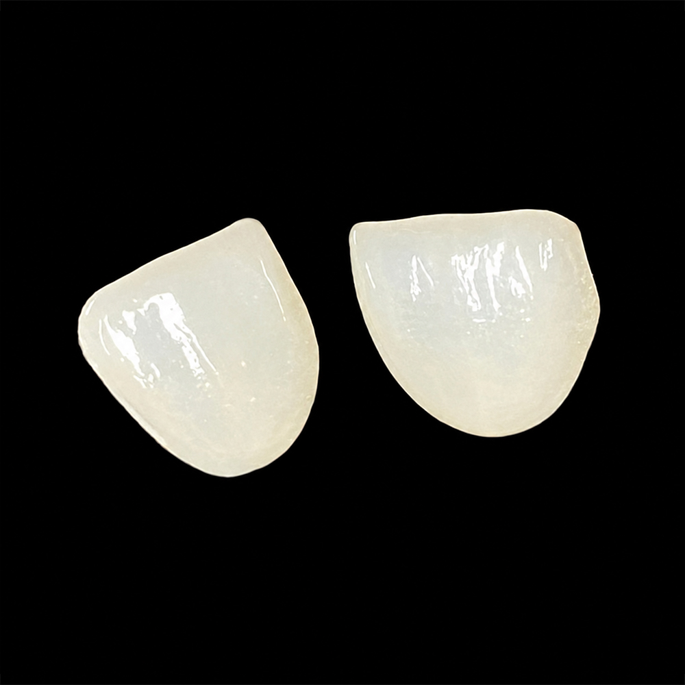
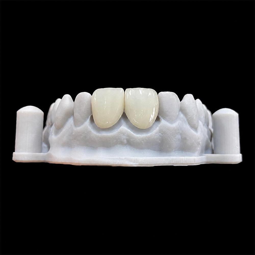
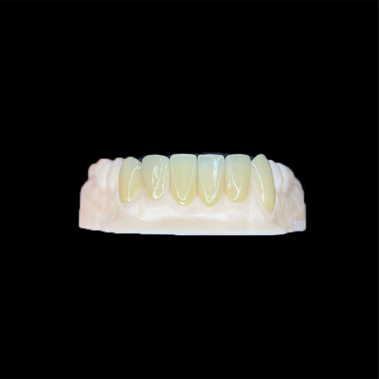
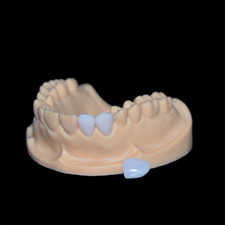
Chipped margins on milled E.max veneers rarely trace back to a single cause. Usually, a thin, poorly supported edge of lithium disilicate meets a round milling tool, cutting forces, heat, and finishing steps that the edge geometry cannot tolerate. The scan or the digital design often set that geometry long before the block reached the mill. For clinicians ordering E.max veneers from a laboratory, the useful question is not who is at fault. It is at which stage the margin failed and which part of the data or process caused it. This article explains the mechanisms, shows how to trace a chip back to its source, and lists what to confirm before the next case.
Why Do E.max Veneer Margins Chip During Milling?
E.max veneer margins chip during milling because the finish line is the thinnest and least supported part of a brittle glass-ceramic, and CAD/CAM milling removes material mechanically with a tool that has a physical radius. IPS e.max CAD-type blocks are supplied in a partially crystallized state, milled first, then crystallized in a furnace to reach their final lithium disilicate structure. That pre-crystallization state is easier to cut, but it is also more fragile than the finished ceramic. A margin that tapers toward zero thickness therefore meets cutting force with almost no material behind it.
Researchers quantify the result with a “chipping factor,” the ratio of chipped margin length to total margin circumference. The metric is discussed alongside research on marginal chipping of lithium disilicate crowns produced by CAD-CAM systems. It is useful for buyers because it turns “the margins look rough” into something a lab can measure and track.
Material choice changes the picture too. In an in-vitro typodont study of laminate veneers, zirconia showed a lower chipping factor than lithium disilicate when both were milled. That result comes from one laboratory model, so treat it as a direction rather than a clinical rule. In that model, lithium disilicate was less tolerant of the same edge conditions than zirconia.
Where Did the Chip Happen? A Diagnostic Table
“Chipped during milling” is often a guess. The same defect can appear at five different stages, and each stage points to a different root cause. The table below is a diagnostic framework built from ceramic-processing logic and technician discussions. It is not a measured failure-rate ranking.
Where the chip is first seen
Likely causes to investigate
What to verify with the lab or in the file
On the milled blue-state restoration, before crystallization
Worn bur or spindle runout, interrupted coolant, aggressive milling strategy, margin designed thinner than the tool can reproduce
Bur replacement routine, milling strategy used for veneers, margin thickness setting, machine maintenance
After sprue removal or hand finishing
Sprue attached too close to the finish line, finishing pressure on a thin edge
Sprue location, finishing protocol, magnified inspection before and after
After the crystallization firing
Micro-damage from milling that was not visible beforehand, handling between milling and firing
Margin inspection before firing, handling procedure, whether the same spot recurs across units
At try-in or seating
Tight contact or internal interference, uncontrolled seating pressure on a thin margin
Occlusion, preparation substrate, margin position relative to function
Pattern recognition helps more than any single measurement. If the chip appears at the same location on several units or several cases, such as the same proximal corner, suspect the data: the scan, the margin line, or the design settings. If chips appear at random locations across different restorations, suspect the process: tool condition, coolant, milling strategy, or handling. This is a working heuristic, not a proven classification, but it keeps a remake discussion from turning into an argument.
Process Causes Inside the Mill
Tool geometry and wear
A milling bur has a finite tip radius and a finite cutting edge. Geometry that thins to a feather edge is exactly what a round tool reproduces least cleanly, because the ceramic wedge at the edge has little mass to resist the tool’s cutting force. As burs wear, cutting forces rise, which stresses that edge further. Spindle runout adds vibration on top.
Direct evidence here is thin. In a lab-technician thread about crescent-shaped fractures above the margins of milled e.max CAD restorations, participants suggested overheating, speed, and poor irrigation, and none confirmed a cause. One or two forum threads cannot establish how often any factor occurs. They do show which questions experienced technicians ask first, and buyers can ask the same ones.
Coolant, heat, and milling strategy
Lithium disilicate blocks are generally milled wet, so coolant delivery matters. Interrupted irrigation raises heat and friction at the tool-ceramic interface, which is one plausible route to micro-damage at the edge.
Strategy matters as well. A 2025 in-vitro study on the influence of milling strategy on the marginal fit of chairside lithium disilicate crowns compared the fastest and finest settings on 40 crowns. The finest strategy always gave better marginal fit for both IPS e.max CAD and Celtra Duo. That study measured fit, not chipping, so it does not prove that finer milling prevents chips. It does show that milling parameters change what happens at the margin. Faster strategies also shorten machine time, which gives a lab a commercial incentive to use them.
Sprue and nesting position
The point where the restoration is attached to the blank holder has to be cut or ground off later. If it sits near the finish line, the removal step can chip the thinnest part of the veneer. Asking where the sprue is placed relative to the margin is a simple, specific question for a lab.
Data Causes Before the Mill: Scan, Margin Line, and Design
A margin the scanner never captured
A common upstream failure is a finish line that was not recorded. When the scan misses a shallow or subgingival margin, the technician has to estimate where the veneer should end. Artist Dental Lab’s guide on scanning veneer preparations without losing thin finish lines explains why a scanner can show a smooth margin it did not actually capture. If the margin is drawn too far coronally, part of the preparation stays uncovered. If it is drawn beyond the tooth, the restoration gets an unsupported overhang of very thin ceramic, which is the geometry most likely to chip when milled.
Margin thickness is not the only lever
The usual advice is “make the margin thicker.” That is partly right, but it oversimplifies. In the typodont veneer study mentioned above, reducing veneer thickness from 0.5 mm to 0.3 mm did not significantly change the chipping factor for either ceramic tested. The same abstract reports that different ceramics chipped differently. In that model, edge geometry, material, and machining conditions mattered at least as much as nominal thickness.
The practical reading: do not assume that a 0.1 mm change in a design setting is what separates a clean margin from a chipped one. Also, do not assume that a razor-thin digital margin is more precise. Past the point the tool can cut, it is just more fragile. Which thickness is appropriate depends on the block, the indication, the machine, and the manufacturer’s current processing instructions, so confirm these with the lab rather than relying on a general number.
Where the margin terminates
Margin position changes how much ceramic is available at the edge. When a proximal margin ends right at the contact, the ceramic often tapers to its thinnest point exactly where the technician is also shaping the contact. Extending the margin deliberately can often move the junction out of view and give the edge more body, but over-extension creates its own cervical contour problems. The lab’s article on interproximal extension for veneers covers how to hide margins without overcontouring.
The same principle appears in crowns. Lithium disilicate generally needs more margin bulk than zirconia, a point Artist Dental Lab’s comparison of how margin design differs between zirconia and E.max crowns works through. Veneer margins are not crown margins, but the underlying logic carries over: the material sets how thin the edge can safely be.
Is Milled E.max the Right Process for a Very Thin Margin?
Sometimes the better fix is a different route. The table compares options qualitatively. It does not rank them by measured chipping rates, because no single verified dataset covers all of them.
Option
How margin chipping risk shows up
Trade-offs to weigh
Consider it when
Milled monolithic lithium disilicate
Tool-edge limits and pre-crystallization fragility at thin margins
Repeatable fit and shade across units; depends on data quality and mill condition
Multi-unit cases with clear, continuous margins
Pressed lithium disilicate
Not milled, so tool-edge limits do not apply; finishing and investment removal bring other risks
Different workflow steps, different handling risks
The design needs an edge the mill cannot cut cleanly
Layered E.max (base plus porcelain)
Added veneering layer adds technique sensitivity and another interface
More esthetic freedom, more variables
Demanding single-unit anterior work
Zirconia veneer
Lower chipping factor than lithium disilicate in one typodont study
Different optical behavior and bonding protocol
Thin edges and function matter more than maximum translucency
Feldspathic porcelain
Not milled; fragile and dependent on enamel support
Highest optical subtlety, least forgiving of poor support
Conservative enamel-bound preparations
Choosing between full and layered construction has its own consequences, and Artist Dental Lab’s explanation of full E.max versus layered E.max veneers describes the monolithic route as the lower-variance option, with the added veneering layer introducing more interfaces and chipping opportunities. For a wider comparison across materials, the margin structure analysis of feldspathic, E.max, and zirconia frames each as a different risk profile rather than a ranking.
One caution runs against the common instinct. A chipped margin does not automatically mean the lab’s machine or the E.max material is poor. A well-run mill still cannot reproduce a margin the scan never captured, and a premium block cannot rescue a feather edge. Equally, the lab should not blame the clinician until it has checked its own bur log and coolant. Both sides own part of the margin.
What Should You Confirm Before Your Next E.max Veneer Case?
A short pre-case check reduces the odds of a chipped margin and makes any problem easier to diagnose:
Margin visibility. Confirm the finish line is continuous and exposed, and inspect the scan at high magnification before sending it.
Margin type and location. Note whether proximal margins end at the contact or extend past it, and flag any feather-edge areas.
Material and process. State whether you expect milled monolithic, pressed, or layered, and why.
Records. Send the preparation scan, opposing scan, bite registration, photographs, shade information, and margin notes.
Lab inspection routine. Ask how margins are inspected before and after crystallization, and at what magnification.
Process questions. Ask about bur replacement routine, milling strategy for thin restorations, and sprue placement relative to the margin.
Remake terms. Agree in advance how chipped margins are assessed and who decides on remake versus acceptance.
None of these questions assumes bad faith. They define who checks what, which is where most disputes about chipped margins start.
Frequently Asked Questions
Why do E.max veneer margins chip during milling?
The finish line is the thinnest, least supported part of a brittle ceramic. A round milling tool, cutting forces, heat, and a feather-edge design can exceed what the pre-crystallization lithium disilicate can tolerate. Scan or design errors often set up the problem before milling starts.
Is a chipped margin the lab’s fault or the clinician’s?
Either, or both. Chips that repeat at the same location across units usually point to scan, margin-line, or design data. Chips at random locations point more to tool condition, coolant, milling strategy, or handling. A review of both sides’ records settles it better than assumption.
Does a thinner margin always chip more?
Not necessarily. One in-vitro veneer study found no significant chipping-factor difference between 0.5 mm and 0.3 mm thickness. Edge geometry, material, tool condition, and machining settings all contribute. Confirm the appropriate thickness for the specific block with the lab and the manufacturer’s current instructions.
Should a veneer with a chipped margin be seated?
It depends on the chip’s size and location. A chip through the finish line can affect marginal seal and cement exposure. The clinician should assess it under magnification. Remaking is often safer than polishing, because polishing can thin the edge further.
Does milled E.max chip more than pressed E.max?
There is no universal answer. Milled restorations face tool-edge limits and pre-crystallization fragility. Pressed restorations avoid milling but carry investment-removal and finishing risks. Compare labs by margin inspection routine and remake records instead of assuming one process is always safer.
What should I send the lab to help prevent chipped margins?
Send a preparation scan with a clearly visible finish line, opposing scan, bite registration, photographs, shade information, and margin notes. Flag feather-edge or subgingival areas, and state the intended material and construction so the lab can adjust design and processing.