価格・サンプルに関するお問い合わせ
ジルコニアクラウン、二ケイ酸リチウムクラウン、ベニア、OEMサービス、あるいは修復物の卸売り注文を比較検討している歯科技工所、歯科医院、販売代理店、および調達担当者の方へ。.
取り扱い製品の種類、素材、月間販売数量、輸出先国、およびサンプルのご要望をお知らせください。営業チームが適切な対応策を講じることができます。.

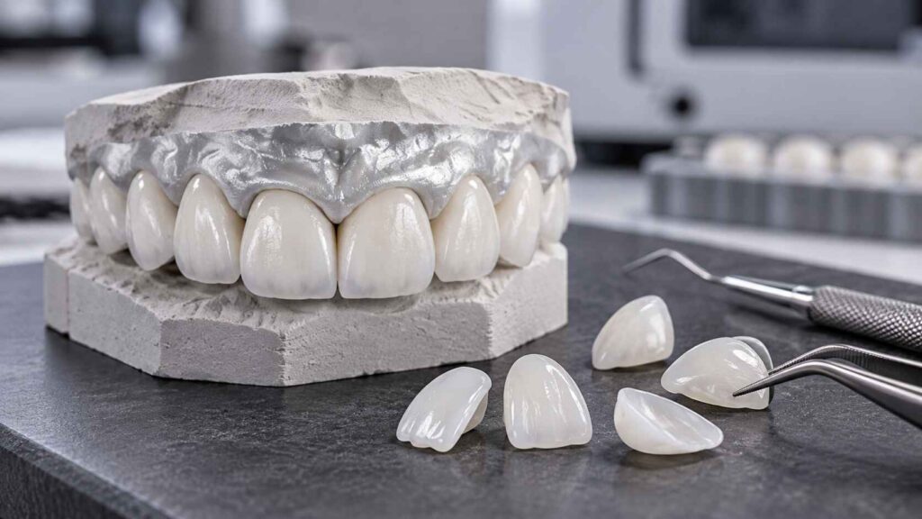
Zirconia veneer cement space is the planned gap that CAD software leaves between a veneer’s internal surface and the scanned preparation. For a restoration only 0.3–0.5 mm thick, it is one of the few design parameters that decides whether the veneer drops onto the tooth, binds against it, or sits with an open margin. Set the space too small and resin cement has no escape path, so the veneer may stop short of its try-in position. Set it too large and the cement layer thickens, margins can open, and the ceramic wall may lose design room. No single micrometer value suits every scanner, software platform, mill, zirconia grade and preparation. This guide explains which settings matter, what published research does and does not show, and what to document before ordering.
In dental CAD software, cement space is the digital offset between the restoration’s intaglio surface and the die. Platforms use different labels, such as cement gap, spacer, luting space or additional spacing. Many split the offset into zones instead of applying one number everywhere. In a public technician forum, one lab described running a cement gap of 0.080 and an extra cement gap of 0.110 in 3Shape while still receiving “friction fit” complaints. That example shows the practical point: two fields can exist, and changing one does not necessarily fix a seating problem.
A typical zoned setup includes:
The programmed value is an instruction, not a measurement of the final cement film. Milling tool geometry, zirconia sintering, finishing, contact adjustment and the viscosity of the resin all change what ends up between ceramic and tooth. The laboratory-side discussion of seating pressure and cement film thickness in ultra-thin veneers covers the clinical half of that story. The same cement-space setting can produce different final films depending on cement rheology and how evenly the veneer is seated.
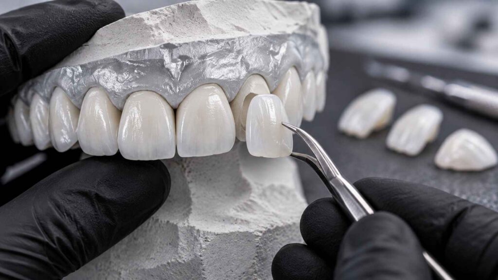
A full-coverage zirconia crown has axial walls, retention form and enough ceramic volume to tolerate some spacer error. A zirconia veneer depends on adhesive bonding and on a precise finish-line and insertion-path relationship. Small offsets also take up a larger share of the restoration.
Consider an illustrative example, not a case study. A veneer designed with a 0.4 mm facial wall and a 50 µm internal offset has an offset equal to one-eighth of the wall. Suppose the outer contour is fixed by the smile design and the software measures minimum thickness before the spacer is applied. The finished wall can then end up thinner than the thickness map suggested. Some systems check thickness after the spacer, others do not. Buyers should ask which applies in the laboratory’s workflow.
The same offset also changes the optical stack. Zirconia, resin cement and tooth substrate all contribute to final color when ceramic is thin, so a thicker cement line is not only a mechanical variable. The article on nesting zirconia veneers in multilayer blanks explains why thickness, stump shade and cement shade should be considered alongside blank position.
Published studies agree on one thing: the digital setting changes fit. They disagree on the best value, because systems, restorations, measurement points and parameters differ.
| Study (design) | Restoration and material | Settings compared | Reported finding | Scope limit |
|---|---|---|---|---|
| Kale et al., J Prosthet Dent 2016 (in vitro, 15 typodont molars) | モノリシックジルコニアクラウン | 25 µm at margin; extra space above margin of 30, 40 or 50 µm | Mean vertical marginal discrepancy was 85, 68 and 53 µm respectively | Crowns, measured before cementation |
| Digital cement space and marginal discrepancy, 2026 (CAD-CAM study) | モノリシックジルコニアクラウン | 80, 100 and 120 µm | Mean marginal discrepancy of 33.35, 31.36 and 28.37 µm; no significant overall difference, but localized differences at two measurement points | Crowns; a much higher range than the study above |
| Micro-CT occlusal veneer study (60 resin dies) | Occlusal veneers in a hybrid ceramic and a zirconia-reinforced lithium silicate | 30, 40 and 50 µm | 50 µm significantly improved marginal fit in both materials | Occlusal veneers, not zirconia and not facial laminates |
| Bennani et al., 2025 (60 veneers, typodont) | CAD/CAM zirconia laminate veneers | Feather edge, shoulder, shoulder with wings preparations | Both shoulder designs produced less overall cement thickness than feather edge; shoulder with wings was thinnest vertically | Tests preparation geometry, not spacer value |
Three conclusions hold up from this evidence.
Numbers do not transfer between systems. One study works in the 30–50 µm range and another in the 80–120 µm range, and each draws conclusions only within its own setup. Generic zirconia guides also quote different ranges. A value copied from a different mill, software version or parameter field is a guess.
Direction depends on the parameter. In the first row, a larger extra space coincided with smaller marginal discrepancy. In the 2026 study, enlarging the space from 80 to 120 µm made no overall difference. Marginal space, internal space and occlusal space behave differently, so “tighter is better” and “looser is safer” are both too simple.
Preparation geometry can matter as much as the software number. The 2025 zirconia veneer study found cement thickness varied with finish-line design when the veneers were otherwise made with the same process. A spacer change cannot compensate for a preparation that restricts the seating path.
No study found in this research isolated zirconia laminate veneers of 0.3–0.5 mm at several cement-space values with measurement after cementation. That is a real evidence gap. It is why laboratory validation data matters more than a rule of thumb.
The table below separates the parameters buyers can ask a laboratory about. It describes failure tendencies in general terms and does not recommend numerical values, because those depend on the validated production system.
| CAD parameter | What it controls | Risk if too small | Risk if too large | What to ask the laboratory |
|---|---|---|---|---|
| Marginal (cervical) space | Gap at the finish line | Premature margin contact, incomplete seating, cement trapped at the margin | Wider marginal gap, more exposed cement line | Value used, and how it was validated on this mill and zirconia |
| Extra spacing and start height | Where the larger internal offset begins | Binding in the cervical third | Less guidance from the preparation, thicker cement film | Start distance from margin and why it suits a thin veneer |
| Internal (facial/axial) space | Overall cement film | Hydraulic resistance, rebound after pressure | Thick cement, optical change, higher modeled adhesive stress | Whether the setting differs from the lab’s crown defaults |
| Incisal or occlusal space | Fit over an incisal overlap | Interference at the edge, wrong incisal position | Instability at the edge | Whether the design is window or overlap, and the insertion path |
| Proximal contact strength | Tightness against neighbors | Veneer stops at the contacts, so it looks like a spacer problem | Open contacts, food impaction | Contact setting and whether contacts are verified on a model |
| Minimum thickness check | Ceramic wall after spacer | Weak or optically thin zones | Not applicable | Whether the thickness map is calculated after the spacer |
| Tool compensation and sintering scaling | Final dimension after milling and firing | Tight, distorted or undersized restoration | Oversized restoration | Zirconia lot scaling, bur compensation, furnace program documented |
Several of these settings interact. A designer who increases the internal gap to cure tightness may be treating a proximal contact or undercut. The critical QC points in a digital veneer workflow list the CAD review items together: margin continuity, spacer start position, cervical cement-space setting, internal relief, contact intensity, insertion path and undercuts. That checklist is a useful template for an RFQ.
No. The common assumption is that a smaller digital gap produces a closer restoration. The studies above show it holds for some parameters in some systems, but fit measured before cementation is not the same as seating on the day.
A tight setting leaves little room for resin to escape. For a veneer 0.3–0.5 mm thick, extra resistance can lead to incomplete seating, or to a thin ceramic wall being forced into place. The opposite correction has its own cost. Widening the gap by default produces a thicker cement line, can shift the marginal fit, and reduces ceramic thickness if the outer surface is fixed. The lab’s seating-pressure discussion cites a finite-element model in which thicker cement layers raised adhesive stress. That points toward a thin, uniform and complete layer, which means neither the smallest possible gap nor the largest tolerable one.
The condition that matters is whether the veneer seats passively and repeatedly on a verified die. If it does, the existing setting is probably working, and further adjustment is unnecessary. If it does not, the spacer is one candidate cause, not the first one to blame.
Technician discussions suggest that spacer changes are often used to compensate for other variables. In another public forum thread, a technician reported needing a higher cement gap for zirconia milled for printed models than for conventional models before restorations would seat. Two threads are anecdotal and do not show how common the problem is, but they match the logic that model manufacturing tolerances can masquerade as cement-space problems.
Work through the chain in order:
For the manufacturing stage, the laboratory QC standards for ultra-thin zirconia veneers recommend seating the restoration more than once. If it only seats with pressure, rocking or selective manipulation, they advise investigating internal interference. They also list spacer settings among the CAD/CAM items to document. A laboratory that records the spacer, thickness map and post-sinter seating check can troubleshoot a remake. One that does not can only repeat the process.
Cement-space control is a process question rather than a number. Compare suppliers on these points:
Avoid choosing a supplier based on a quoted “perfect fit” figure with no measurement method, location or sample size.
Cement-space performance depends on the inputs supplied with the order. A purchasing or clinical team should prepare:
について zirconia veneer product page lists STL scans, shade and stump shade, occlusal notes, photos and smile design goals as the information to send. It also names fit, margins, contacts and finish uniformity as QC focus areas. Confirm the cement-space handling for your case in writing before production, because the product page does not state a specific setting.
No universal value exists. Published studies use ranges from 30–50 µm to 80–120 µm, depending on the system and parameter. The right setting is the one a laboratory has validated for its software, mill, zirconia grade and veneer design.
Not always. Extra space gives resin more escape room, but binding can also come from tight proximal contacts, undercuts, printed-model error, sintering distortion or margin interference. Diagnose the cause before changing the setting.
It can. If the outer contour is fixed, a larger internal offset reduces the available ceramic wall. Ask whether the laboratory’s minimum-thickness check is calculated before or after the spacer is applied.
No. The setting is a design instruction. Final film thickness is also affected by milling, sintering, finishing, resin viscosity, preparation geometry and seating pressure, so measured cement layers can differ from the programmed number.
Include clear scans with a visible margin, scanner or model details, preparation design, zirconia grade, stump and target shade, planned cement system, and a request for documented spacer values and a post-sinter seating check.
Not first. Check the scan margin, model accuracy, contacts, insertion path and post-sinter distortion. If those are verified, adjust one spacer parameter at a time and record the result for the next production batch.